Saturday, April 4, 2020

Xlights and the RPi Again - The End

Xlights

This is the software that breathes life into the lights! It is the most creative part of the process. Xlights is a popular option in the Christmas lighting community. It was originally called Nutcracker.

Here is a description of how to install Xlights on a Windows computer: https://xlights.org/hrf_faq/how-to-install-xlights-on-windows/

A great way of getting to know Xlights is to follow the Quick Start Guide in the User Manual here: https://manual.xlights.org/xlights/

Below are the main points for setting up Xlights for each tab.
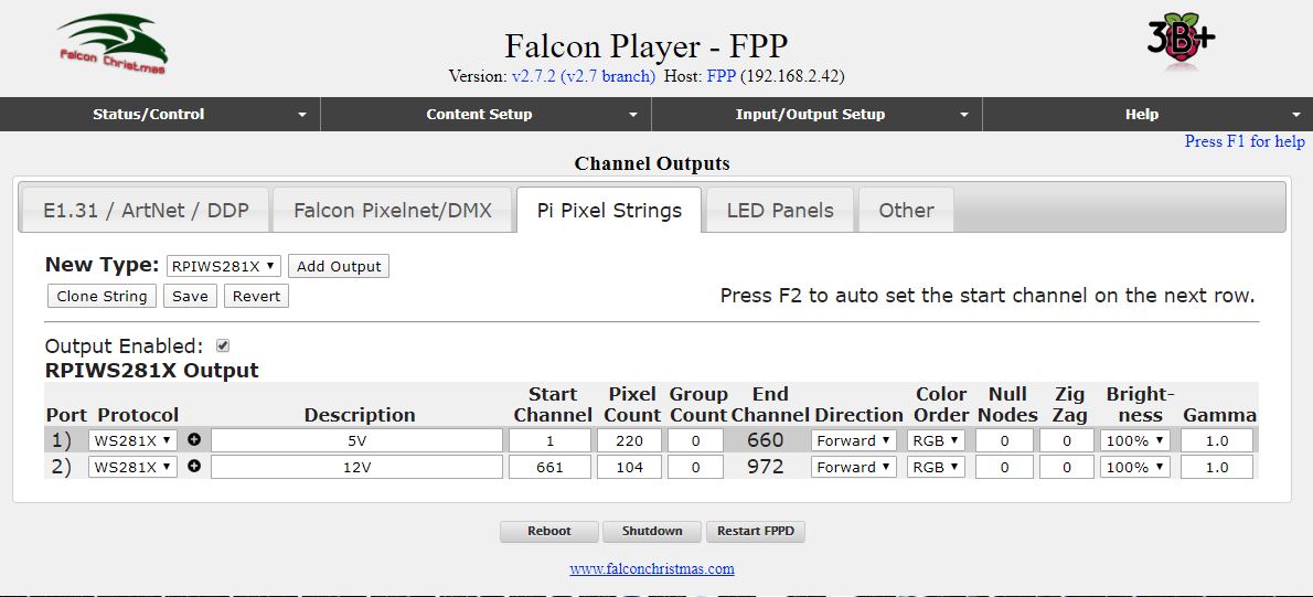
Setup Tab

No need to enter anything in this tab since the RPi is doing all the work.

Layout Tab

I uploaded a photo of the front of my house that included all the lighting locations. Reduced to 50% brightness in Xlights so the lighting overlay is more easily seen.

The 5V strings...

For the snowflake, click on the Download button which is the down-pointing arrow, second from the right, then click on the house photo and drag out to the right size in approx the actual location of the snowflake. In the new window that opens, select the ChromaFlakes 24" 3 prong Fancy which is the name of this coro ornament. Then click on Insert Model.

Now to set up the addressing. Since this is the first string, the Start Channel is 1 (this field is located in bottom-left box). The end channel is automatically set at 144 since there are 48 pixels in the snowflake (48 pixels x 3 LEDs in each pixel = 144).

The next ornament is the bauble. This is not yet available in the system so I created a custom model. This is described here: https://youtu.be/d9JbDvwzoiQ

I decided the order in which the LEDs would be inserted into the back of the bauble and added them to the matrix. I uploaded it for others to use here: https://drive.google.com/drive/folders/0B2ozCEidtWh3MUdWM3hhNENzazQ

To get the bauble on the screen, click on the Import button which is third from the right then click on the house photo and drag out to the right size, then select the bauble model (which will end in .xmodel) from where it was saved

The first pixel of the bauble will be immediately after the last pixel of the snowflake, so Start Channel is "Boscoyo ChromaFlake 24 3 prong:1".

The last ornament is the candy cane. Click on the Download icon then click on the house photo and drag out to the right size. In the new window that opens, select the ChromaCane 48 which is under Christmas and Candy Canes. Then click on Insert Model. The Start Channel is "Boscoyo ChromaElement 13:1" because it is immediately after the last pixel of the bauble.

The 12V strings...

The first pixel in the 12V string is the first floodlight. There is no specific button to select a floodlight so I created one from the Single Line button. Drag a shape onto the house photo as usual. Change the name to 'Flood 1'. 

The control wire for the 12V strings comes from the controller, it does not continue from the end of the 5V string. However the controller treats it as if it continues from the end of the 5V string, so the Start Channel is "Boscoyo ChromaCane 48:1" which is after the last pixel in the candy cane. Change Nodes/String to 1.  Under Appearance, change the Pixel Size to 100, Pixel Style to Blended Circle and Black Transparency to 50.

Next is the strings of 50 LEDs. Initially I wound these around the column at the front of my house. This resulted in quite a few of the LEDs being at the back of the column and out of sight which I felt was a waste. I remounted them going up and down the front of the column four times, so there were 4 lines on each column each going in the opposite direction to the one next to it. To model this in Xlights I created four Single Lines on each column. The first line has 13 pixels, the second has 12, the third has 13 and the last has 12. I called them Single Line 1-1, Single Line 1-2, Single Line 1-3 and Single Line 1-4. The Start Channel of Single Line 1-1 is Flood 1:1.

Next is the second floodlight. Insert it onto the photo, name it Flood 2 and fix its settings as for Flood 1. Start Channel is the end of Single Line 1-4.

Next is the second string of 49 LEDs (was 50 but I destroyed one of them!).  I broke these into 4 Single Lines named Single Line 2-1, Single Line 2-2, Single Line 2-3 and Single Line 2-4. The Start Channel of Single Line 2-1 is Flood 2:1.

Next are the remainder of the floodlights. The Start Channel of Flood 3 is Single Line 2-4 and the Start Channel of the subsequent flood light is the previous flood light.

This is what the Layout tab looks like.


Now that the configuration is done it's time to add life to the lights...

The Sequencer Tab

Select the New Sequence button (green folder) and select Animation (since I don't have any musical accompaniment) then select 40fps (the fastest option) then Quick Start. This will bring all of the models into the main window. Experiment with dragging and dropping effects into each model and reviewing the results in the House Preview window. Use the Play (green arrow in the top bar) to preview the sequence. Select the colours used in the Color window. Save the sequence with the save button (blue disk).

The Final Steps

The Falcon Player will control the lights each night as a stand-alone device - your home computer and Xlights do not need to be running. To do this, the sequence that I have just designed and saved in Xlights needs to be uploaded into the Falcon Player. Fortunately this function is built in to Xlights.

Here is a description of the next process: https://manual.xlights.org/xlights/chapters/chapter-five-menus/tools/fpp-connect

In Xlights, from the Tools menu option, select FPP Connect. Xlights then searches the network for the Falcon Player and brings up the 'FPP Upload' window which shows the Falcon Player and lists the sequences that are available. In the top section of the window tick the Upload checkbox, the Media checkbox and the PiHat checkbox. FSEQ Type is V2 Sparse and UDP Out is None. In the bottom section tick the checkbox next to the sequence to be used by the Falcon Player. Then click the Upload button to upload the selected items to the Falcon Player.

Now just a couple more steps to go... setting up the sequence in Falcon Player. This is described well by Canispater Christmas here: https://www.youtube.com/watch?v=ODSKccObZI4.

Go to the browser and call up the Falcon Player. From Content Setup menu select Playlists. In the New Playlist box type a name for the playlist and click Add to create a new empty playlist. This will appear in the Playlist Details below. Type is 'Media and Sequence' and for the Sequence enter the name of the sequence that was uploaded from Xlights and click Add. The sequence will appear in the Main Playlist below. Then click on Save.

Now go the Scheduler which is the next option in the Content Setup menu. Add the playlist and the daily start and stop times. Click the Save button. Everything should now be ready to go. From the Status Control / Status Page click on Restart FPPD and the sequence should start playing and the lights should be operating to the programmed schedule.

And that's it!!

Sunday, March 15, 2020

Setting up the Raspberry Pi

Falcon Player

The software to be loaded on the Raspberry Pi is called Falcon Player, previously known as Falcon Pi Player (FPP). The name was changed because it also works with other single-board computers, particularly the Beagle Bone Black (BBB).

There is a great YouTube video from Canispater Christmas which describes the whole sequence here: https://www.youtube.com/watch?v=X95Rv4JGG_Y

He uses an Apple computer but everything works the same for Windows computers.

Alternatively there is another great YT video here: https://www.youtube.com/watch?time_continue=257&v=3QcAJOwAfF4&feature=emb_logo

In short, this is the procedure I followed:


  1. Buy a 16Gb micro SD card class 10 or better 
  2. Download the latest Falcon Player software from github at this link: https://github.com/FalconChristmas/fpp. It will be under Releases and at the top of the list. Look for Pi in the file name.
  3. Format the card. Most new cards are already formatted but if not then can download and use the software called 'SD Card Formatter'.
  4. Put the Falcon Player software on the SD card. This is called imaging. Download the imaging software called Etcher from etcher.io then use it to put the downloaded Falcon Player software onto the SD card.
  5. Plug the SD card into the RPi.
  6. Connect the power cable to the RPi as well as the network cable to your home router. The RPi will boot up for the first time which will take about 30s. If you have connected a HDMI cable from the RPi to a monitor you will see the Pi booting up - this is just for testing since normally the Pi is not connected to a monitor when running your Christmas lights. The Falcon Player software will start automatically. 
  7. View the Falcon Player software from your home computer by opening your favourite browser (I use Chrome) and in a new tab type FPP. If this doesn't work try http:fpp or http:fpp.local. If none of these work you will need to use the IP address assigned to the Pi by your home router. To get this you will need to visit your router web page which will usually be 192.168.x.1 where x is your network number, usually 1. Look for the device called FPP and take a note of the IP address and enter that into your browser.
  8. I will be storing the lighting sequences on the SD card so I'll expand the storage available on the SD card for the file system - in the Falcon Player select the Status/Control pulldown menu then Advanced Settings then Grow Filesystem then 'Go to FPP Main Status Page' then Reboot.

Connecting the LEDs

Now for the exciting part... checking that the Raspberry Pi works with the LEDs.

I powered-up the control board (the control board is described in an earlier post) and connected a string of pixels to the terminal strip at the bottom for the field wiring. Could have been 5V or 12V or both, just needed to be sure to connect to the correct terminals. In the Falcon Player from the Status/Control pull-down menu I selected Display Testing which is the last option and clicked on Enable Test Mode to start the test. And the pixels lit up Red then Green then Blue!! Yay!!


Addressing

Each pixel has a unique number. The first pixel is number 1, the next along is number 2 and so on to the last pixel in the string. Then the first pixel in the next string starts where the other one finished. 

In my system the first string is the 5V string because it is connected to Channel 2 (marked CN2) on the Hanson cape on the RPi. This is the first channel with pixels connected since Channel 1 is not used in this system, and is known in the Falcon Player as Port 1. The 12V strings are connected to Channel 3 so their numbering starts where the 5V strings finish, and they are connected to Port 2.

Since I have 220 pixels in the 5V system the pixel count is 220. This is entered in the Falcon Controller in the Pi Pixel Strings tab in the Channel Outputs section which is found in the Input/Output Setup menu.


There are 3 LEDs in each pixel and each LED is considered a Channel, so the 220 pixels become 660 channels, so the end channel is 660 and the start channel of the second port is 661. There are 104 pixels in the 12V system so that is entered as the Pixel Count for the second port and the end channel is calculated as 972.

I started with 105 pixels in the 12V system (5 floods + 2 strings of 50 pixels each) but I managed to blow up one of the pixels in one of the strings (by connecting it with the wrong polarity I think) so I cut out that pixel and my count reduced by one.

The screen shot above is my final configuration. None of the other tabs in the Channels Outputs screen need to be changed.

That is the end of the configuration of the RPi... well almost. The final step is to set up the playlist and this is done after the sequences have been programmed in Xlights. That is the next blog entry.

Saturday, March 14, 2020

Connecting Everything

The Ornaments

The 5V pixel strings need to be pushed into the coro. This is more difficult than it looks! Use gardening gloves or a pixel-pusher (yes they exist!).

The order in which the pixels are loaded into the coro is important otherwise the software patterns won't work correctly. The numbering is provided in the Xlights software. Details in a later post.

Connecting the cables

After mounting the coro ornaments, the 12V strings and the floodlights (with lots of cable ties!), the next task was to connect up the power cables (2 wires) and the control cable (1 wire).

I bought a cable crimping tool and a box of assorted crimping connectors from eBay. I bought some other connectors from Bunnings and Jaycar which were more expensive but I noticed that the connectors from eBay were made with much thinner copper which is probably why they often didn't make a strong grip on the wire.

These are the connections to be made:


I my design I didn't use any injection, so only the first diagram applied.

The biggest challenge and the most time-consuming part of the process was getting a 3-way connection on the 'fat' power cable. I tried a number of techniques (soldering cables of this size is very difficult) and the best was a three-way crimp connector I found in the box of connectors from eBay.


To provide insulation and basic waterproofing I wrapped the connections in electrical tape. Luckily (?) there was a drought and it didn't rain over the Christmas period so waterproofing was not an issue. Next time I plan to 3D print some junction boxes.

I joined the control cable with smaller crimp connectors. Next time I think I will solder these cables as it provides a much more reliable connection and is easy to do with these thin cables, and I can use heatshrink. Elsewhere I have tried using heatshrink with silicon sealant in each end to form a waterproof seal and it seems to work well.

Some photos of the end result.


The snowflake

The candy cane

Connection to a flood and string

Floodlight on the house

Floodlight on the garage door


Wiring to the Pixels

Connecting the Lights

All my pixels are the 3-wire type (not 4-wire). Two wires are for power and the third is the control signal wire. The control signal is how the controller passes its commands to the first pixel, which squares up the signal and passes it to the next pixel and so on. The power cables provide the power to light up the LEDs.

Many people use pre-made cables and connectors which is the easiest to connect the cables and ensure waterproofing. The size of these cables is usually 0.75mm2 which would not be sufficient to carry all the power for my system (minimum is 1mm2 for the 12V and 1.5mm2 for the 5V) so I would require multiple runs from the power supply to the pixels. I think many people do this however I wanted to have just a single run of cables out from the controller to the pixels (actually 2 runs, one for the 5V and one for the 12V). My aim was to make it simpler to connect with less wires.

The Control Wires

The control wire is easy since it carries almost no power. I used solenoid wire from Bunnings that I had left over from my automatic sprinkler system. 

The distance from the controller to the first pixel, and the maximum distance between pixels is limited as the signal is quite a high frequency. In my system the longest run of the signal cable between pixels is about 6m and I didn't have any problems.

If this had been a problem I would have used a 'null pixel' which is never illuminated by the software but re-shapes the control signal so it can travel to the next pixel.

The 5V control cable went like this:

  1. from the controller to the start of the snowflake
  2. from the end of the snowflake to the start of the bauble
  3. from the end of the bauble to the start of the candy cane

The 12V control cable went like this:


  1. from the controller to the first flood
  2. from the first flood to the first string
  3. from the end of the first string to the second flood
  4. from the second flood to the start of the second string
  5. from the end of the second string to the start of the third flood
  6. from the third flood to the fourth flood
  7. from the fourth flood to the fifth flood

The Power Cable

There are two demands on the power cable. One is to deliver the current and the other is to deliver the voltage. Earlier I have calculated the current (different for each string voltage) so now let's think about the voltage...

Voltage drop is caused by the current running through the resistance of the cable. The resistance of the cable is determined by its length and cross sectional area (to be technical it also depends on the type of metal, but in this case it's always copper, and the temperature but let's not get into that detail). Long skinny cables have the greatest resistance, short fat cables the least. The resistance per metre for the different sizes of cable is provided in the 101 guide and other tables on the internet.

5V Pixel Strings Cables

I'll start with the strings of 5V 50 pixels since the cable size and length is fixed - it is 0.75mm2 at 12cm spacing with Ray Wu's products. The resistance per metre for this cable is 24.5mOhm/m. So the resistance from one pixel to the next is 0.12 x 0.0245 x 2 = 5.88mOhms. The x 2 at the end is because the current has to go back over the same length.

Now to calculate the voltage drop. Ohms law tells us that voltage drop = current x resistance. Think about the very last pixel, which at maximum load (white at full brightness) has 55mA through it's cable. [I used 55 not 60mA this time, as an average of some guides that say 50mA and others that say 60mA.] So the voltage drop from the cable is 55mA x 5.88mOhms = 0.3234mV. Notice that the voltage drop is not dependent on whether it is a 5V or 12V pixel. That's because LEDs are constant-current devices.

Now I'll consider the second last pixel. It has 110mA through it's cable because it is powering its pixel and also carrying the current that goes through to the last pixel. So the voltage drop is double that of the last pixel. The third last pixel will have three times the voltage drop. The voltage drop at the very first pixel will be 50 times. The maximum voltage drop which is the voltage drop at the last pixel will be the sum of all the voltage drops is 1 + 2 + 3 + ... + 50 = 1275 x 0.3234mV = 0.412V.

The 12V strings are similar except the distance between the pixels is 14cm so using the same formulas the maximum voltage drop comes to 0.481V.

I experimented with 5V strings connected in series and found that a 5V power supply connected at one end would light all pixels on 2 x 50 pixel strings and some of a third string. Note that the pixels were not white so it was not done at maximum load. When the 5V power supply was connected at both ends, all the pixels in all 3 strings operated. I have read that at the minimum extreme of voltage the colours may not be correct.

Pixels in the Ornaments

The snowflake uses 48 pixels so I cut off 2 pixels from the end of the string. The volt drop multiplier is (1 + 2 + ... + 48) which is 1178, so the maximum volt drop is 1178 x 0.3234mV = 0.381V. The current in the snowflake is 48 x 0.055 = 2.64A.

The bauble has 124 pixels made up of 50 for the outline and 74 for the face. The maximum number of pixels that could be on are the outline (50 pixels) plus the eyes open (20) plus the mouth open (22) = 92 pixels. After seeing the bauble in action my family decided that the face was too creepy so only the outline was used. That makes the maximum volt drop 0.412V (from calc above). The current is 50 x 0.055 = 2.75A.

The candy cane is the same as the snowflake since it also has 48 pixels.

Adding the currents (Kirchoff's current law) gives the currents in all the cables - see the diagram below:


Note how I have designed the circuit so the current for one string does not pass through any others. In other words the strings are connect as a T from the main power supply. This is because the fat supply cable is large enough to carry the current and not drop as much voltage.

Note that this is the power circuit, the control circuit has all the pixels in series as described in the 'Control Wires' section above.

Overall Volt Drop for Ornaments

Now to calculate the voltage drop in the cable connecting the ornaments. Let's do the calcs assuming a 6mm2 cable - I chose this size because it is the largest that can use standard crimp lugs and still bends ok. The resistance of this size cable is 3.08mOhm/m. Let's aim for no more than 5% voltage drop which is 250mV.

The lengths of cable are: 3m from the controller to the snowflake (the first ornament), then 1.5m to the bauble, then 1.5m to the candy cane (the last ornament).

The volt drop in the last connection (from the bauble to the snowflake) is 1.5 x 2.64 x 0.0038 x 2 = 24mV.

The volt drop in the middle connection (from the snowflake to the bauble) is 1.5 x (2.64 + 2.75) x 0.0038 x 2 = 61mV. Need to add the current of the snowflake to the current of the bauble since this cable is supplying both loads.

The volt drop in the first connection (from the controller to the snowflake) is 1.5 x (2.64 + 2.75 + 2.64) x 0.0038 x 2 = 92mV.
Now I'll go through from the start to the end...

The volt drop at the start of the snowflake is 92mV. The volt drop at the start of the bauble is 92 + 61 = 153mV. The volt drop at the start of the candy cane is 153 + 24 = 177mV. 

The volt drop at the end of the snowflake is 92 + 381 = 473mV.
The volt drop at the end of the bauble is 153 + 412 = 565mV.
The volt drop at the end of the candy cane is 177 + 381 = 558mV.


All these are above the nominal limit of 5% drop! I should have added another connection from the power supply to the end of the pixel strings (injection) to fix the volt drop issue. I decided to 'see how it went' and actually it was ok without the injection.

Another alternative would have been to increase the cable size, but I'm not going to go bigger than a 6mm2 cable - too unweildy and more difficult to connect and more expensive.

12V Strings and Floodlights

The pixel strings and floodlights are connected as shown in the diagram. This arrangement best suited the mounting locations for the LEDs.

The maximum string current is 50 x 55mA = 2.75A. The maximum floodlight current is 0.7A from its specification sheet.

By adding the currents (Kirchoff's Current Law) we can find the currents in all the cables:


The maximum volt drop at the end of the 50 pixel string is 0.481V, calculated earlier.

Let's use the same cable, 6mm2 which has 3.08mOhm/m.


Again, should aim for a maximum drop of 5% of 12V which is 600mV.


Volt drop (1) = 4m x 0.7A x 3.08mOhm/m x 2 = 17mV
V (2) = 6 x 0.7 x 3.08 x 2 = 26mV
V (3) = 4 x 2.1 x 3.08 x 2 = 51mV
V (4) = 5 x 5.55 x 3.08 x 2 = 171mV
V (5) = 3 x 2.75 x 3.08 x 2 = 51mV
V (6) = 3 x 9 x 3.08 x 2 = 166mV

Adding the voltages (Kirchoff's voltage law) gives:

Volt drop at flood 1 = V(6) = 166mV
Volt drop at the start of string 1 = V(6) + V(5) = 166 + 51 = 217mV
Volt drop at the end of string 1 = 217 + 481 = 698mV
Volt drop at flood 2 = V(6) + V(4) = 166 + 171 = 337mV
Volt drop at the start of string 2 = flood 2 = 337mV
Volt drop at the end of string 2 = 337 + 481 = 818mV
Volt drop at flood 3 = V(6) + V(4) + V(3) = 166 + 171 + 51 = 388mV
Volt drop at flood 4 = flood 3 + V(2) = 388 + 26 = 414mV
Volt drop at flood 5 = flood 3 + V(1) = 388 + 17 = 405mV

The voltage drops at the end of the strings are above the nominal 600mV limit... the largest is 818mV which is a 7% drop... I'll just live with it (without injection) as I did for the 5V system - and it worked!

I bought a 60m reel of 6mm2 twin core cable from eBay for $150 which is $2.50 per metre, ok I think. This is more length than I need, but will have plenty left over for mistakes and enhancements next year!

Friday, March 13, 2020

The Controller

The Controller

I decided from the start that the controller would be a Raspberry Pi since I have used a few of these around the house including a garage door opener. I bought the latest version which is the 3 B+. If it was a school report card, version B+ would be less than A, but actually B comes after A so B+ is the latest!

I bought the RPi 3+ and 8Gb micro SD card from eBay.


Some device is needed to interface to the pixels. Many people use Falcon controllers. I understand that these are straightforward to use however they are a little more expensive than I had in mind for my first year's display. Instead I used a cape (daughter board) which plugs into the RPi, specifically the Hanson Electronics RPI-28D+ (http://www.hansonelectronics.com.au/product/rpi-28dplus/). It is remarkably inexpensive and it can control two separate WS2811 strings with different voltages. It can also control another string with WS2801 but I didn't need that facility. It can power the RPi from the pixel supply so a separate power supply for the Pi is not needed.

Network Connection

I extended my home network to the controller by running a Cat6 cable to my garage where my controller was to be located. I bought the cable from Bunnings as I find the quality of the cables on eBay to be generally poor.

Many people use Wifi but I found the signal to be weak and unreliable at that location because it is a long way from my modem. Also I found that a power line carrier system didn't work at that location.

Power Supplies

Now the maths starts...

Calculating the size of each power supply... each colour in each pixel requires up to 20mA (0.02A) which means if all 3 colours (R+G+B) are at full brightness such as when showing white, the total is 60mA. Some guides say 50mA so let's just keep the difference up our sleeves as an extra buffer.

Let's start with the 12V circuit.

100 pixels x 60mA = 6A, which at 12V is 6 x 12 = 72W

5 x floods 9W = 45W

So total power requirement is 117W. Allowing maximum load of 85% to make sure the power supply is not overloaded gives 138W.

I took the view that it was unlikely that all pixels would be at full brightness in white, so I selected a 120W power supply since this is the largest standard size available.

Now for the 5V.

200 pixels x 60mW = 12A, which at 5V is 12 x 5 = 60W. Allowing maximum 85% load gives 71W.

I found that 5V power supplies are quite cheap so I purchased one rated at 150W to give plenty of overhead if I add to the load later.

Meanwell is the gold standard but I opted to save money and used generic PSUs from eBay.

Fuses

According to the calculations above, the 24V circuit can draw up to 120W/12V = 10A so I used a 10A fuse. The 5V circuit can draw up to 71W/5V = 14.2A so I used a 15A fuse.

The RPi and cape take very little power so I used a 2A fuse (could have used less).

Rather than try to connect fuses in-line, I bought the Hanson Hexafuse Board (http://www.hansonelectronics.com.au/product/hexfuse/) from Hanson Electronics which takes standard size automotive fuses. I bought a box of fuses with various ratings from eBay.

Crimp connections

I crimped bootlace lugs onto most of the wires to make them easier to put into terminals. I bought a bootlace crimper (https://www.ebay.com.au/itm/301325808452and a box of various size bootlace lugs (https://www.ebay.com.au/itm/153215439554from eBay.

Wiring

The wires before the fuse need to be rated for at least the current rating of the power supply. For the 12V power supply that is 10A so according to the table in the 101 guide the cable should be at least 1mm2 which is AWG17.

For the 5V power supply that is 30A so the cable must be at least 3.6mm2 which is AWG12.

The wires after the fuse need to be rated for at least the current rating of the fuse, so for the 12V wiring that is 10A which according to the table requires a cable size of 1mm2 or AWG17 and for the 5V wiring is 15A which requires 1.5mm2 or AWG15. Easiest just to use 1.5mm2 cable for all the 12V circuits and for the 5V circuit downstream of the fuses.

I had some spare wire already and the rest I bought from eBay.

Terminals

The 12V power supply came with a cable attached to the output so I used terminals to connect it to circuit wires. It needed to be rated at 10A.

The connections from my controller board to the pixels were done through a 50A rated terminal strip.

I bought both the terminals from Bunnings.

Bringing it all Together

Here is the wiring diagram.


And here is what it looks like, using a mounting board made from old bed slats and mounted on the side of the garage, inside, close to the roller door.


Notes on safety

The 240V supply must be connected by a qualified person. 

I notice that the protection against touching the 240V terminals of the 5V power supply is a piece of plastic that is lifted up to connect the wires. This is really dangerous!! Please make sure that a finger-proof barrier is screwed in place (not shown in my photo above).

The Pixels

The Voltage

Most pixels come in a choice of two voltages - 5V or 12V. To cut a long story short, the 5V pixels use less than half the power of the 12V pixels for the same brightness but are not as convenient for longer runs because they will need power injection and/or thicker cables. 

Here is the longer story: 
http://www.holidaycoro.com/kb_results.asp?ID=126
also 
http://www.doityourselfchristmas.com/wiki/index.php?title=Choosing_a_Pixel_Voltage:_5V_vs_12V

For the ornaments I chose to use the 5V pixels to save power. This decision was made from more of a theoretical standpoint because the additional power is not very much for this size display.

The floodlights only came in 12V and since I was planning to run the pixel strings in the same circuit it meant that these needed to be 12V as well. Pity since I was hoping to run them all in 5V.

The Pixel Protocol

Inside each pixel is a chip (IC) that contains and/or controls the LEDs and the communications between the pixels. There are a few different types of chips and they are described well in the ACL 101 manual under the heading 'Intelligent RGB Light IC Types'.

I would have preferred the LEDs to be embedded in the chip which is a WS2812B (one less chip, maybe more reliable) but these were not available from Ray Wu (the supplier of choice for many ACL members) in the configuration I was after.

The 5V pixels I bought use the WS2811 chip.

I bought pixels with a 3 wire system (2 power and 1 control wire) to save on the control wiring. Each pixel has 6 wires - 3 in and 3 out. The alternative is a 4 wire system.

What I bought

Putting it all together, this is what I used.

For the ornaments: 4 x strings of 50 pixels (nodes) WS2811 8mm bullet 5V 3 wire. https://www.aliexpress.com/item/32225918892.html?spm=a2g0s.9042311.0.0.49aa4c4d2xmOSB

For the strings: 2 x strings of 50 pixels WS2811 C9 (large size candles) 12V 3 wire. https://www.aliexpress.com/item/32462921140.html?spm=a2g0s.9042311.0.0.49aa4c4d2xmOSB

Pigtails and end caps to connect to the strings: https://www.aliexpress.com/item/1019853359.html?spm=a2g0s.9042311.0.0.49aa4c4d2xmOSB

For the floodlights: 5 x RGB 9W 12V. https://www.aliexpress.com/item/32827247145.html?spm=a2g0s.9042311.0.0.49aa4c4d2xmOSB

The Display

My display consists of:
  • 3 x Christmas ornaments
  • 2 x strings of 50 LED pixels
  • 5 x LED floodlights on the house
The Christmas Ornaments

The ornaments are made from corrugated plastic and have holes for the 8mm diameter LED pixels (also called nodes). I bought them at the Sydney mini and they are also available online here: https://www.extremelightingdisplays.com.au/ 

I bought a snowflake (Chromaflake 24"), a bauble with a face (ChromaOrnament 13) and a candy cane (ChromaCane mini). They need 48, 124 and 48 pixels each respectively.

The face in the bauble was my favourite but my family decided it looked freaky so I ended up disabling it. So actually I only needed 50 pixels for the bauble.

The Strings

I wanted strings of LEDs but I wasn't sure where I was going to mount them. Since they are a significant feature I chose the cover to be the large style candle called C9. 

I ended up attaching them to the small pillars near my front door. I was hoping for an effect of lights running up and down the pillars but it didn't really work very well. Might change it next year.

The Floodlights

My first idea was to light up the hedge in my front yard but then I realised that the dark leaves would absorb the light. So I decided to light up the house and this turned out well I would say. I bought 6 floodlights but ended up needing only 5 to cover the front of my house with light. My plan was to have sheets of colour moving across my house but that didn't really work so in the end I went with the whole house being the same colour that slowly went through the colour rainbow.

Alternatives

I was going to use strips of LEDs and I had some experience with these before having made a LED sign and an aquarium light and because they are good value for money. I decided against them because they are not as flexible as individual pixels connected by wires.