The software to be loaded on the Raspberry Pi is called Falcon Player, previously known as Falcon Pi Player (FPP). The name was changed because it also works with other single-board computers, particularly the Beagle Bone Black (BBB).
There is a great YouTube video from Canispater Christmas which describes the whole sequence here: https://www.youtube.com/watch?v=X95Rv4JGG_Y
He uses an Apple computer but everything works the same for Windows computers.
Alternatively there is another great YT video here: https://www.youtube.com/watch?time_continue=257&v=3QcAJOwAfF4&feature=emb_logo
In short, this is the procedure I followed:
- Buy a 16Gb micro SD card class 10 or better
- Download the latest Falcon Player software from github at this link: https://github.com/FalconChristmas/fpp. It will be under Releases and at the top of the list. Look for Pi in the file name.
- Format the card. Most new cards are already formatted but if not then can download and use the software called 'SD Card Formatter'.
- Put the Falcon Player software on the SD card. This is called imaging. Download the imaging software called Etcher from etcher.io then use it to put the downloaded Falcon Player software onto the SD card.
- Plug the SD card into the RPi.
- Connect the power cable to the RPi as well as the network cable to your home router. The RPi will boot up for the first time which will take about 30s. If you have connected a HDMI cable from the RPi to a monitor you will see the Pi booting up - this is just for testing since normally the Pi is not connected to a monitor when running your Christmas lights. The Falcon Player software will start automatically.
- View the Falcon Player software from your home computer by opening your favourite browser (I use Chrome) and in a new tab type FPP. If this doesn't work try http:fpp or http:fpp.local. If none of these work you will need to use the IP address assigned to the Pi by your home router. To get this you will need to visit your router web page which will usually be 192.168.x.1 where x is your network number, usually 1. Look for the device called FPP and take a note of the IP address and enter that into your browser.
- I will be storing the lighting sequences on the SD card so I'll expand the storage available on the SD card for the file system - in the Falcon Player select the Status/Control pulldown menu then Advanced Settings then Grow Filesystem then 'Go to FPP Main Status Page' then Reboot.
Connecting the LEDs
Now for the exciting part... checking that the Raspberry Pi works with the LEDs.
I powered-up the control board (the control board is described in an earlier post) and connected a string of pixels to the terminal strip at the bottom for the field wiring. Could have been 5V or 12V or both, just needed to be sure to connect to the correct terminals. In the Falcon Player from the Status/Control pull-down menu I selected Display Testing which is the last option and clicked on Enable Test Mode to start the test. And the pixels lit up Red then Green then Blue!! Yay!!
Addressing
Each pixel has a unique number. The first pixel is number 1, the next along is number 2 and so on to the last pixel in the string. Then the first pixel in the next string starts where the other one finished.
In my system the first string is the 5V string because it is connected to Channel 2 (marked CN2) on the Hanson cape on the RPi. This is the first channel with pixels connected since Channel 1 is not used in this system, and is known in the Falcon Player as Port 1. The 12V strings are connected to Channel 3 so their numbering starts where the 5V strings finish, and they are connected to Port 2.
Since I have 220 pixels in the 5V system the pixel count is 220. This is entered in the Falcon Controller in the Pi Pixel Strings tab in the Channel Outputs section which is found in the Input/Output Setup menu.
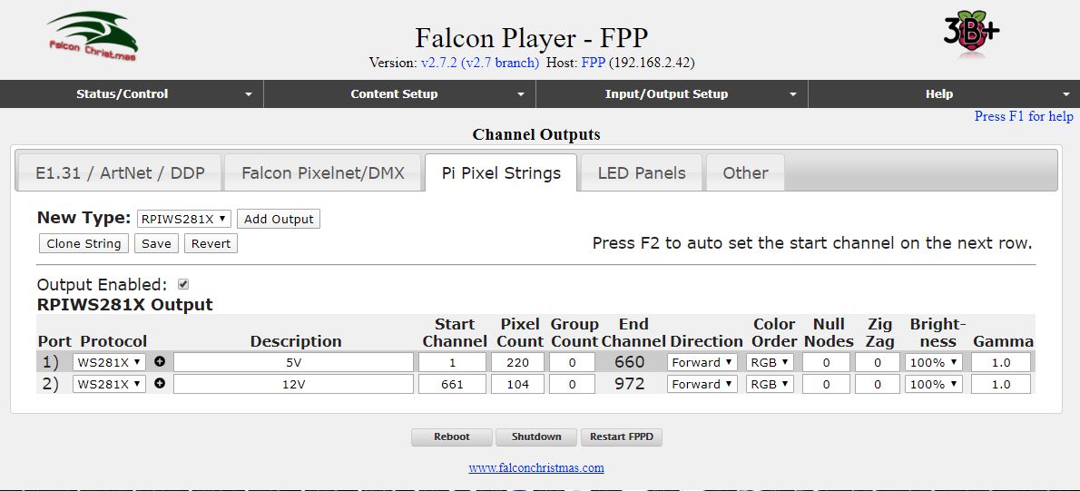
There are 3 LEDs in each pixel and each LED is considered a Channel, so the 220 pixels become 660 channels, so the end channel is 660 and the start channel of the second port is 661. There are 104 pixels in the 12V system so that is entered as the Pixel Count for the second port and the end channel is calculated as 972.
I started with 105 pixels in the 12V system (5 floods + 2 strings of 50 pixels each) but I managed to blow up one of the pixels in one of the strings (by connecting it with the wrong polarity I think) so I cut out that pixel and my count reduced by one.
The screen shot above is my final configuration. None of the other tabs in the Channels Outputs screen need to be changed.
That is the end of the configuration of the RPi... well almost. The final step is to set up the playlist and this is done after the sequences have been programmed in Xlights. That is the next blog entry.
No comments:
Post a Comment